Archives

Choosing Whether or Not To Install Evaporative Cooling

(Also see “Trouble-Shooting” if your cooler is not performing well)

Evaporative Cooling
or
Refrigerated Air Conditioning??

A common question asked by many is “should I install an Evaporative Cooler or Refrigerated Air Conditioning?”

(Please note: The correct terminology is “Evaporative Cooler” and NOT “Swamp Cooler”)

If you live in a coastal or tropical region, you probably never hear the explanation below because “evap cooling” is not very efficient when your ambient air is full of humidity.
(except for use in greenhouses where high humidity is healthy for the plants)

If your wet bulb temperature is around 60% and higher, then refrigerated cooling is the correct answer.
In lower wet bulb regions a properly sized evaporative cooler can be a very cost- effective and comfortable choice.

Sizing the evaporative cooler is the key

A good “rule of thumb” is to have 1 air change every 3 minutes in northern states, 1 air change every 2 minutes in the mid section and 1 air change every 1-2 minutes in the southern states.

.
The Rule of Thumb formula for sizing your cooler is very simple;

Multiply the length by the width by the height of the area to be cooled to get the cubic footage for the area. Then divide by your air change factor minutes. The example below reflects a “2” minute air change.


Example:

A home that is 30′ wide, 40′ long and 8′ ceiling has a total of 9600 cubic feet of area to be cooled.
30 x 40 x 8 = 9600
Using the factor two (for an air change every two minutes),
divide 9600 by two to give you the CFM required, in this case, 4800 CFM.
9600 / 2 = 4800

In this case, you would want to use a 4800 CFM cooler.
(Note: It never hurts to go one size up. You might consider a 5500 CFM cooler here)
The cooler can be run on low speed, then cranked up to High on severe days.


Another important factor is “Exhaust Air’. A good cooler design is to exhaust slightly more air than your cooler is supplying, this can be done with windows or doors being open slightly or a sized exhaust fan inter-locked with the cooler.

Having enough air exhausted is important so that there is negative air pressure in the conditioned space, positive air will cut down your blower’s capacity. A big advantage to evap coolers is that the capacity can be changed easily by adjustable pulleys to increase or decrease air flow. If you open your front door and the pressure slams it shut then, you need more exhaust openings, such as a window or another door.

(Ample air exhausted also reduces the humidity build up)

Refrigerated air conditioning cools no matter what the humidity is and usually increases your home value (as well as your electric bill) more than an evap cooler, but with a well designed evaporative cooling system installed, cost is less to install and hardly noticeable on your utility bill.

A few notes for evaporative cooler maintenance:

The more frequent aspen cooler pads are changed the better – don’t try to get 2-3 years out of pads. Twice a season is best (although seldom done). Be sure to change aspen pads at the beginning of each season when starting up your cooler.
(An exception to this is using a cooler with a celdek type pad, such as our UltraCool)
The pads can easily be used for five years or more when the cooler is properly installed with a bleed off system.

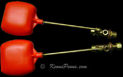
A properly installed bleed off system can prolong the life of your pads and greatly reduce the corrosion affects on your cooler. Below are two types that can be used.

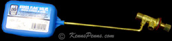
Bleed Off Kit System
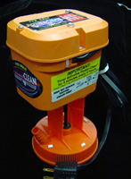
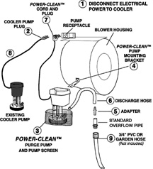
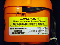
Power Clean Purge Pump System
(Purge Pump Conserves More Water)

Oil the motor and bearings – Most evaporative cooler motors do have oil ports. Use SAE #20 non-detergent oil.
Do not use motor oil. It has detergent content. This will reduce the life of your bearings.

Check for proper belt tension, and amp draw. (Overloading the amp draw will burn the motor out)

INADEQUATE COOLING
(just a few tips – there are many more things to check out)
This should be done by a qualified technician

PROBABLE CAUSE
SUGGESTED REMEDIES
Cooler undersized
Replace with larger cooler
Clogged or dirty filters
Replace with new pads
Dry pads or lack of water while cooler is operating
Check water distributing system for possible obstruction in tubing. Check pump operation.
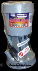
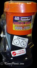
Replace Pump if necessary
Insufficient air discharge openings or inadequate exhaust from area being cooled, causing humidity building up and discomfort

Evaporative coolers must have large enough ductwork
Ductwork sized for refrigeration simply will not let the higher cfm from a cooler out.

Make sure there is adequate provision for exhausting air from area being cooled.
 
Excessive humidity.
(See also item above re: inadequate exhaust)
In some areas, there may be a few days during the summer when the relative humidity is high, resulting in poor cooling. (60% or higher) These are limitations of an evaporative cooler under conditions of high wet bulb temperature.
Blower turning backwards
Reconnect motor for correct direction.
Blower installed backward
Remove and reinstall blower wheel to turn in correct direction.
Blower running too slow
Check motor amps. If below nameplate amperage, readjust variable pitch motor pulley to increase blower speed. Do not increase amperage above motor rating. This will burn the motor out.

Why Is There An Odor From My Newly Installed Cooler Pad?

When a new Rigid Cooling Media pad is installed in evaporative coolers, there is usually a slight odor emitted.
This slight odor will dissipate and be gone after a short period of time.

When these pads are first wet out a slight odor may occur from the dust created when the pad is manufactured and cut to size.

THIS ODOR IS NOT TOXIC OR HARMFUL.

The operation of this type cooling pad requires a wet out period (typically several hours without airflow) followed by draining and refilling the sump water pan. This will remove the small amount of residue in the media that would be the source of the odor. This operation may have to be repeated on larger systems that do not drain completely.

All evaporative cooling systems have odor problems related to the system cleanliness. This is how ‘swamp coolers’ first got its name. When left UN-cleaned, they would start to smell like a swamp. All cooling media require cleaning, both initially, and ongoing. All cooling pads of this type are manufactured using the same base resin materials and have the same odor associated with them. All new cooler pads have a ‘new pad’ odor that dissipates with use. Once the pads are ‘broken in’, this odor will disappear. The once active ingredients in the paper of the cooling pad are rendered inert during the manufacturing processing, however, the odor from these materials lingers until the pads are washed clean by the wetting process after installation.

Click Here For:
Installation Instructions

Evaporative Swamp Cooler Thermostats

Visit the Order Info Page to Order!
Email For Special Quote on Very Large Quantities

* Please Note, There Is A $25 Minimum Charge PLUS S/H For Cooler Parts Orders

Installation Instructions Shipped With All Thermostats
Free shipping
Free Shipping on all Thermostats

P/N 7617 Cooler Controller ™

2 Speed 1/3 HP to 1 HP 115/230 Volt
Automatically Controls the operation of an Evaporative Cooler

P/N 7619 Cooler Thermostat
$69
Includes Free Shipping

Automatically controls the operation of the evaporative cooler.
LCD digital temperature readout with electronic temperature sensor circuitry.
Constant room temperature displayed.
Easy single touch temperature adjustment.
Case door covers operating controls
Four-minute blower start delay when using pump feature for pad wetting.
Installs in standard depth 2 x 4 single gang electrical box.

UL Listed, 1 HP, 115 VAC, 60Hz


P/N 7619 Cooler Thermostat

Thermostat Wall Plate
P/N 7616
Wall Plate
Adapts Digital Thermostat Controller to a 2 gang electrical junction box

$6

Installation Instructions Shipped With All Thermostats

P/N 7625 EZIStat Controller ™

2 Speed 1/3 HP to 1 HP 115 Volt and 230 Volt
Automatically Adjusts Motor Speed
Also Has Manual Control for 2 / 4 / 8 Hour Timer Mode

P/N 7621 EZIStat

No Longer Available

Automatically adjusts from High to Low speed
as the temperature approaches set point.
Optional manual control for cool (pump) and fan only
2 / 4 / 8 hour timer mode
Automatic start and stop – in “Cool” Mode only
Simple 5 wire interface
Installs in standard 2 x 4 single gang electrical box

P/N 7621 EZIStat

Thermostat Wall Plate
P/N 7616
Wall Plate
Adapts Digital Thermostat Controller to a 2 gang electrical junction box
$6

Installation Instructions Shipped With All Thermostats

P/N 7620 SELECT-A-STAT Cooler Controller ™

2 Speed 1/3 HP to 3/4 HP 115 Volt
Bimetal temperature sensing with unique heat anticipator
Line voltage thermostat & controller
Includes switches to control pump & 2-speed motor (15 amps)

P/N 7620 Select-A-Stat
 NO LONGER AVAILABLE
Automatic start & stop for temperature control
Includes separate control of high and low-speed blower motor and control of pump
Bimetallic sensing element
Includes thermostat, motor switch, pump switch, leads and installation wiring diagram
Installs easily with 4 lead wires and ground terminal
Designed for installation in single gang or double gang electrical boxes (not included)
Rated 15 amps at 115 volts VAC. UL Listed

Installation Instructions Shipped With All Thermostats

Replacement Window Cooler Grills and Covers

Visit the Order Info Page to Order!
Email For Special Quote on Very Large Quantities

* Please Note, There Is A $25 Minimum Charge PLUS S/H For Cooler Parts Orders

Replacement Window Cooler Grills For Champion/Marquis Brands Only
The Grills & Winterizing Covers Below Are Designed to Fit Champion Brand
Window Coolers Only
Check dimensions of grills & covers shown above

We do not Guarantee they will fit any other cooler brands

Grills & Covers are NOT SUBJECT FOR RETURN

New Champion Window Cooler Grill
Part No. 110839-1
Fits Newer Model Champion Window Coolers
Made After 2003

Old Champion Window Cooler Grill
Part No. 310833-001
Fits Older Model Champion Window Coolers
Made Before 2004

NO LONGER AVAILABLE

Part No. 110839-1
$69

Grill Dimensions
21 1/2″ x 13 7/8″

Part No. PSA-10833-002
WITH SWITCH & KNOB

NO LONGER AVAILABLE

Grill Dimensions
25″ x 12 1/4″

Winterizing Window Cooler Ridgid Plastic Grill Covers For Champion/Marquis Brand Only

Champion WCM28 Grill
Part No. 310834-101

Fits Older Model Champion WC28 or WCM28
(switch in the center)

NO LONGER AVAILABLE

Champion Window Cooler Grill Cover
Part No. 110829
$56  Free Shipping
Only Fits Champion Model Window Coolers Only
Made After 2003

DOES NOT FIT
WC 28 OR WCM 28 COOLERS

Part No. 310834-101

 NO LONGER AVAILABLE
Grill Dimensions
21 1/2″ x 11″

Part No. 110829
$56

Includes Free Shipping
Fits Grill Measurement of
21 1/2″ x 13 7/8″
The Above Grills & Winterizing Covers Are Designed to Fit Champion Brand
Window Coolers Only
Check dimensions of grills & covers shown above

We do not Guarantee they will fit any other cooler brands

Grills & Covers are NOT SUBJECT FOR RETURN

* Please Note, There Is A $25 Minimum Charge For Cooler Parts Orders

Ceiling Diffusers Wall Grills

Visit the Order Info Page to Order!
Email For Special Quote on Very Large Quantities

* Please Note, There Is A $25 Minimum Charge PLUS S/H For Cooler Parts Orders

#7637 Plastic Ceiling Diffuser
Diffuses Air 4 Ways or 6 Ways

With 14 Adjustable Louvers
White High Impact Plastic
Will Not Rust, Corrode or Stain

Overall Size of Grille is

22 1/2″ x 22 1/2″ x 3 1/8″ Depth

For Duct Openings
16″ x 16″ up to 20″ x 20″

Plastic Ceiling Diffuser
#7637 Plastic Ceiling Diffuser

$49 Plus $17.50 UPS shipping
$66.50 Total

Plastic Side Wall Register
#7700 Series Plastic Registers

have been DISCONTINUED.

7791
6 x 6
2 Way
 
7792
8 x 6
2 Way
 
7794
12 x 6
3 Way
 
7795
14 x 6
3 Way
 
7796
16 x 6
3 Way
 
7797
20 x 6
3 Way
 
7799
14 x 8
3 Way


Ceiling Grill
#7700 Series Plastic Register
Ceiling

7788
8 x 8
4 Way


See Description & Features Below

~ 7700 Series Plastic Registers~

Are No Longer Available

As of 8/2/11 these registers are no longer available.

#7700 Series Plastic Side Wall Registers

And

#7700 Series Plastic Ceiling Registers

Sizes shown are width and height for inside duct hole

Add 2″ to width and height for outside dimensions

Plastic cooler, heating, and air conditioning vents are economical and practical

Will not rust

Cleans with soap and water

Pull to open, push to close for damper operation

Built in opposed blade damper effect for system balancing

Attractive brush finished trim that can be painted to match decor

Easy to install, mounting screws and installation instructions included

Evaporative Swamp Cooler Wall Switches

Visit the Order Info Page to Order!
Email For Special Quote on Very Large Quantities
* Please Note, There Is A $25 Minimum Charge PLUS S/H For Cooler Parts Orders
RSK 2 Wall Switch Wiring Diagram
RSK 2 Wiring Diagram

Click Here For Window Cooler Grill Switches


RSK 2 Rotary Wall Switch
For Side Draft And
Down Draft Coolers

(see wiring diagram on left)

Cooler Wall switch
RSK 2
$25

Note!
$25 Minimum Charge For Parts OrdersClick Here For Window Cooler Grill Switches

WARNING:
HOUSE VOLTAGE CAN BE LETHAL

1. Turn off power before installing the switch. The installer of this switch must be technically qualified for this type of installation. A qualified electrician should check all wiring and circuit breakers and be sure that the cooler installation is effectively grounded.

2. Refer to evaporative cooler installation instructions and all applicable electrical codes for correct installation of the evaporative cooler, switch and wall switch box, correct wiring procedures, and effective grounding.

3. Motor and pump voltage and amperage must not exceed switch specifications. This switch is recommended for 120-volt applications only.

4. This diagram is a basic schematic and is not intended to represent all methods of installation because of various cord, plug, and pump configurations. See evaporative cooler installation instructions and motor and pump instructions for proper motor and pump wiring. Be sure motor, pump, and cooler are properly grounded. Color coded wires must not be interchanged or interconnected with each other.

5. CAUTION: Turn the switch to “OFF” position before turning power on.

Evaporative Window Cooler Switches

Visit the Order Info Page to Order!
Email For Special Quote on Very Large Quantities
* Please Note, There Is A $25 Minimum Charge PLUS S/H For Cooler Parts Orders

Click Here For Cooler Wall Switches

Typical Wiring For
PART NUMBER 110425
FOR ALL
Champion Brand Window Cooler Switcheswiring diagram #1

Champion Window Model Wiring Diagram

Typical Wiring For

OTHER Brands Window Cooler Switches

(NOT CHAMPION BRAND)
P/N 7212 & P/N 7225

wiring diagram #2
Other Brand Window Switch Wiring

Wiring Diagrams Sent With All Switches

See Terminal Connections on Back Side
of Switches Shown on The Right
to Determine The Switch P/N
You Need

wiring diagram #3
P/N 7221 Wiring Diagram
SPECIFY P/N 110425 SWITCH
FOR ALL
CHAMPION BRAND
WINDOW MODEL COOLERS

Click Here For Wall Switches

WARNING:
HOUSE VOLTAGE CAN BE LETHAL

1. Turn off power before installing the switch. The installer of this switch must be technically qualified for this type of installation. A qualified electrician should check all wiring and circuit breakers and be sure that the cooler installation is effectively grounded.

2. Refer to evaporative cooler installation instructions and all applicable electrical codes for correct installation of the evaporative cooler, switch and wall switch box, correct wiring procedures, and effective grounding.

3. Motor and pump voltage and amperage must not exceed switch specifications. This switch is recommended for 120-volt applications only.

4. This diagram is a basic schematic and is not intended to represent all methods of installation because of various cord, plug, and pump configurations. See evaporative cooler installation instructions and motor and pump instructions for proper motor and pump wiring. Be sure motor, pump, and cooler are properly grounded. Color coded wires must not be interchanged or interconnected with each other.

5. CAUTION: Turn the switch to “OFF” position before turning power on.

Click Here For Wall Switches


Window Cooler Switches
Below

Chamjpion Cooler Short Stem Switch
P/N 110425
Fits Champion
Window Coolers Only
(see wiring diagram #1 on left)
$24
Cooler Switch Knobs Below

P/N 110839-006
Newer Models
Left Knob Image
Above
$8
P/N 110836
Older Models
Right Knob Image
Above
DISCONTINUED

See Below For Other Cooler Brands Switches

All Other Brands
Window Cooler Switches
Below
(see wiring diagram #2 on left)
Short & Long Stem Switch

P/N 7212
DISCONTINUED
(P2-3006-1)
Short Stem
Switch
No Longer Available 

P/N 7225
DISCONTINUED
(P2-3006-3)
Long Stem
Switch
No Longer Available 

Long Stem Switch
P/N 7271
Old
(P2-171)
DISCONTINUED
Long Stem
Switch
No Longer Available

Window Switch Knob
Switch Knob
Front View
$7

P/N 7450
Short Shank Knob
P/N 7481
Long Shank Knob
Window Switch Knob -side view
Side View of Knob

Note!
$25 Minimum Charge Plus S/H
For Parts Orders

POWER CLEAN KIT ®

Power Clean Purge Pump

P/N 1540 Power Clean Kit
115 VOLT
$83
Includes S/HP/N 1542 Power Clean Kit
230 VOLT
$87
Includes S/H

Free Shipping
UPS Regular Ground
AUTOMATICALLY FLUSHES YOUR COOLER
5 Minutes After Every 8 Hours of Cooler Pump Use
MINUTES TO INSTALL

POWER-CLEAN® Kit includes…

Purge Pump
Mounting Bracket
Mesh pump screen
30 inches of 1/2 inch I.D. vinyl drain hose
Drain hose to overflow pipe adapter
Installation instructions

Visit the Order Info Page to Order!
Email For Special Quote on Very Large Quantities

Click Here To See Installation InstructionsTimer activates Power-Clean®
For 5 Minutes Every 8 Hours

Does Not Replace Existing Water Pump
Does Not Replace Existing
Cooler Pump

Power Clean Special Plug
Power-Clean Plugs Into Receptacle
Existing Cooler Pump
Plugs Into The Back Of The
Power-Clean Plug

Saves water and money
Freshens air
Prevents mineral build-up
Reduces maintenance
Pads last longer
Fits all coolers


Power Clean Installation Instructions

CAUTION:

  • Disconnect electrical power to cooler before installing your POWER-CLEAN ® system or servicing cooler
  • Installation must comply with cooler manufacturer’s specifications and all applicable building and electrical codes. For safety against electrical shock, cooler cabinet, blower motor, pump(s) and switch(es) must all be properly grounded.

INSTALLATION PROCEDURE:

  • Disconnect Electricity to Evaporative Cooler.
  • Unplug Pad Pump
  • Place Pump Screen Onto POWER-CLEAN ®
  • Pump.Mount POWER-CLEAN ® Pump Inside Cooler. Secure pump to blower housing with mounting bracket.
  • Install Hose Adapter Into Overflow Pipe. Place proper end of hose adapter into overflow pipe. See markings on hose adapter.
  • Attach 1/2″ Hose From POWER-CLEAN ®
  • Pump To Hose Adapter. Securely attach hose onto pump. Connect other end of hose onto hose adapter. Avoid kinking hose — cut hose if deemed necessary.
  • Plug-In POWER-CLEAN ® Pump. Note the specially integrated plug and receptacle on the POWER-CLEAN ® pump cordset.
  • Plug-In Pad Pump. Plug your pad pump into the specialPOWER-CLEAN ® pump receptacle.
  • Connect Piping To Remove Cooler Water. Do not allow cooler water to run onto the roof. Connect garden hose, or 3/4″ PVC piping from the underside of the cooler drain to an appropriate drain site on the ground. Use of 45-degree elbows instead of 90-degree elbows is recommended. This will prevent unsightly roof stains as well as potentially damaging effects to roof shingles.
  • Reconnect Electricity to Evaporative Cooler.
  • OPERATING:Your POWER-CLEAN ® system automatically removes the water in your cooler once *every 8 hours that the cooler pad pump is “ON”. This periodic draining replaces the ‘hard’ water that naturally develops in the cooler with clean, fresh water in a consistent manner. The result is decreased scale build-up, longer pad life, less cooler maintenance and lower water usage (compared to a standard bleed-off system).

IMPORTANT:

  • POWER-CLEAN ® drains the water depth to less than 1/2 inch.
  • During the POWER-CLEAN ® draining cycle, both purge and pad pumps are “on”.

CONTENTS:

1 POWER-CLEAN ® Purge Pump

1 Mounting Bracket

1 Pump Screen

*1 Pump Hose (1/2″ I.D., 30 inches long)

1 Hose Adapter (Purge Pump Hose to Overflow Pipe)

Note for Tucson, Arizona Area Installations:

Certain building/electrical codes require the use of a “P-26 Fuse Box”, such as the G.E. Model No. T-U261F rainproof power outlet fuse box when wiring a cooler.

When using this fuse box, a fuse rated at 1.6 Amp might be required for proper operation of the POWER-CLEAN ® system vs. the smaller 1.25 Amp fuse. These fuses are a type S time delay and must be used ahead of the cooler pump and POWER-CLEAN ® system.


LIMITED WARRANTY:

  1. Purge Pump is warranted under normal use and recommended maintenance for 2 years from date of sale to user. In event of defect or failure, replacement is made through your authorized dealer or retailer.
  2. Reason for replacement, purchase date, and sales receipt mustaccompany pump returned for replacement.
  3. Warranty is void if pump has been abused, altered, water damaged or improperly installed.
  4. We do not pay the cost of a service call at the site of installation to diagnose cause of trouble, or the cost of labor or transportation to replace a defective pump.
  5. We are not responsible for any incidental or consequential damage resulting from any malfunction unless required to do so by state law.

Evaportative Swamp Cooler Pumps and Float Valve Assemblies

We Stock Residential & Industrial
Evaporative Swamp Cooler Pumps
& Brass Float Valve Assemblies

UL 6500

Residential Coolers


UL 11000
UL 21000

Industrial Coolers

NOR 120 Marquis Pump
NOR 120
Marquis Cooler Pump
DISCONTINUED
NOT LONGER AVAILABLE


1/4″ Brass Float Valve
1/4″ Compression Connection Only
Fits All Residential Coolers

We Recommend Brass Body Float Valves
NOT PLASTIC BODY
Brass Body is More Durable

3/8″ Brass Float Valve
For Large Industrial Coolers
Specify Iron Pipe or Compression Connection
P/N 4178   For   3/8″        Iron Pipe Connection
P/N 4164   For   3/8″       Compression Connection
Model No.
Description
Pump
Cost
Brass Float Valve Assembly
UL 6500
115 Volt
For All Residential Model Coolers
$ 35
+$12 S/H
1/4″
$9
UL 11000
115 Volt
For Up To 11,000 CFM
$ 39
+$12 S/H
3/8″
$15
UL 11000
230 Volt
For Up To 11,000 CFM
$ 41
+$12 S/H
Specify
P/N 4178 3/8″
Iron Pipe Connection
UL 21000
115 Volt
For Up To 21,000 CFM
$ 47
+$13 S/H
P/N 4164 3/8″   Compression Connection
UL 21000
230 Volt
For Up To 21,000 CFM
$ 50
+$13 S/H
Specify Voltage For
Pump Orders
* Please Note, There Is A $25 Minimum Charge PLUS S/H For Cooler Parts Orders
Click Here For Ordering Information